
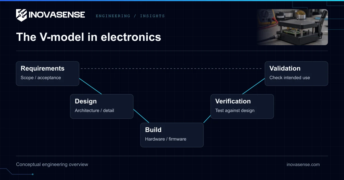
What is the V-model in electronics development?
The V-model is the established systems engineering methodology for hardware development, where every design phase on the left side of the "V" has a corresponding verification phase on the right side. Unlike agile software development (where iterating is cheap), hardware iteration is expensive — a PCB respin costs €5,000–50,000 and delays a project by 4–8 weeks. A comprehensive, structured approach isn't bureaucratic overhead; it's the only way to predictably deliver hardware on time and on budget.
Why Hardware Projects Fail
Before examining the methodology, it’s worth understanding what goes wrong in projects that don’t follow one:
| Failure Mode | Root Cause | Cost of Late Discovery |
|---|---|---|
| EMC non-compliance | No pre-compliance testing before certification lab | €3,000–5,000 per failed test + 4–8 week respin |
| Thermal shutdown | No thermal simulation, works at 25°C but fails at 55°C | PCB redesign, new heatsink/enclosure tooling |
| Power supply instability | Inadequate decoupling, missing SPICE simulation | Board respin, potential component damage in field |
| Component obsolescence | No lifecycle check on BOM components | Redesign around replacement part, new PCB revision |
| Regulatory gap | Certification requirements not considered in architecture | Fundamental architecture change, project restart |
Every one of these failures is preventable with proper upfront planning and structured verification.
The V-Model in Practice
Left Side: Design Decomposition
1. Requirements Definition (2–4 weeks)
- Functional requirements (what the product must do)
- Non-functional requirements (temperature range, EMC class, IP rating, certifications needed)
- Interface specifications (connectors, communication protocols, mechanical constraints)
- Regulatory requirements mapping (CE, FCC, MIL-STD, medical class, ATEX zone)
2. System Architecture (1–2 weeks)
- Block diagram with defined interfaces between subsystems
- Technology selection trade study (MCU vs SoC vs FPGA, wireless protocol, sensor selection)
- Power budget analysis (total current draw, battery sizing, thermal dissipation estimate)
- Preliminary BOM with component availability and lead time verification
3. Detailed Design (4–8 weeks)
- Schematic capture in Altium Designer or KiCad
- PCB layout with impedance-controlled stackup for high-speed signals
- SPICE simulation of power supply, analog circuits, and critical signal paths
- Signal integrity simulation for DDR, high-speed serial, and RF traces (HyperLynx, Ansys HFSS)
- Mechanical integration (3D model, thermal simulation, DFM review)
Bottom of the V: Build
4. Prototype Fabrication (3–6 weeks)
- PCB fabrication (typically 4–6 layer, FR-4 or Rogers for RF)
- Component procurement and incoming inspection
- SMT assembly (pick-and-place, reflow, through-hole)
- Initial bring-up and power-on testing
Right Side: Verification (Maps to Design Phases)
5. Unit Testing (verifies Detailed Design)
- Individual subsystem verification (power supply output voltage, ripple, efficiency)
- Peripheral communication (SPI, I²C, UART, CAN waveform analysis with logic analyzer)
- Analog circuit performance (gain, bandwidth, noise floor)
6. Integration Testing (verifies System Architecture)
- Complete system functional testing
- Firmware integration and system-level debugging
- Communication protocol validation (wireless range testing, packet error rate)
- Power consumption profiling (Nordic PPK2 or Otii Arc for µA-level measurement)
7. System Verification (verifies Requirements)
- EMC pre-compliance (conducted/radiated emissions, susceptibility)
- Environmental testing (thermal cycling -40°C to +85°C, vibration per IEC 60068, humidity)
- Safety testing (dielectric withstand, leakage current, ground continuity per EN 62368-1)
- Regulatory certification submission (CE marking, FCC Part 15, specific industry certifications)
8. Acceptance Testing (verifies Requirements Definition)
- Customer acceptance criteria validation
- Field trial / pilot deployment
- Production readiness review
Communication: The Hidden Success Factor
In outsourced development, communication quality directly determines project outcomes:
- Weekly status reports — Progress against milestone plan, open risks, decisions needed
- Design review meetings — Formal reviews at each gate (CR, DR, PR, DV, PV) with documented minutes and action items
- Issue tracking — Every bug, design question, and change request tracked with priority and owner
- Change control — Any requirement change after Design Review requires formal change request with impact assessment (cost, schedule, certification)
The most expensive words in hardware development are “while we’re at it, can we also…?” without a corresponding change control process.
Quality Metrics We Track
| Metric | Target | Why It Matters |
|---|---|---|
| First-pass yield | >95% | Measures manufacturing quality and design robustness |
| EMC pre-compliance pass rate | >80% first attempt | Early testing catches issues before expensive lab visits |
| Requirement traceability | 100% coverage | Every requirement has a corresponding test |
| BOM dual-source coverage | >90% of line items | Supply chain resilience |
| Design review action closure | 100% before next gate | Unresolved actions compound into late-stage failures |
At Inovasense, the V-model isn’t a document — it’s how every project is structured. Each milestone gate has defined entry/exit criteria, and we don’t proceed until the previous gate’s deliverables are complete and reviewed. This disciplined approach is why our projects deliver on time and pass certification on the first submission. Contact us to start with a proper requirements review.
Sources & Official References
- ATEX Directive — 2014/34/EU — EUR-Lex (Official Journal of the EU)
Frequently Asked Questions
What is V-Model in hardware development?
V-Model is the established systems engineering methodology where every design phase (left side of the V) has a corresponding verification phase (right side). Requirements → Architecture → Design → Implementation flow down, then Unit Verification → Integration Testing → System Validation flow back up. For electronics it prevents costly respins by validating each phase against its specification before moving forward.
How does V-Model differ from agile development?
Agile assumes cheap iteration — software bugs are patched and redeployed in hours. Hardware iteration costs €5,000–50,000 per PCB respin and adds 4–8 weeks of delay. V-Model frontloads verification activities so design errors are caught before fabrication. The two methodologies are not mutually exclusive: firmware inside hardware projects often uses agile sprints within an overall V-Model framework.
How much does a PCB respin cost?
A typical 4–8 layer PCB respin costs €5,000–€50,000 including prototype fabrication, assembly, components, engineering re-work, and bench re-verification. Add 4–8 weeks of project delay. For RF or high-speed designs above 1 GHz, respin costs reach €30,000–€100,000+ due to specialized fabrication and EMC re-testing requirements.
Is V-Model required for ISO 26262 or DO-254 certification?
Functional safety standards (ISO 26262 for automotive, IEC 61508 for industrial, DO-254 for airborne electronics) explicitly mandate phase-based development with traceability between requirements, design, and verification — which is the V-Model. Without V-Model documentation, certification audits will fail. The standards do not name it as V-Model but require its core structure.
What are V-Model verification phases for hardware?
Five verification phases mirror the design phases: (1) Unit verification — schematic review, simulation, component selection validation; (2) PCB verification — design rule checks, signal integrity simulation, manufacturing review; (3) Integration testing — first-article inspection, functional bring-up; (4) System validation — environmental testing, EMC pre-compliance, performance characterization; (5) Acceptance testing — customer acceptance against original requirements.
How long does a V-Model hardware project typically take?
Typical timeline: 2–4 weeks requirements + architecture, 4–8 weeks detailed design + simulation, 4–6 weeks first prototype fabrication + bring-up, 4–8 weeks integration + iteration, 4–6 weeks certification testing. Total 18–32 weeks for moderate-complexity products. Defense and medical projects with formal verification take 12–24 months.
Can V-Model be applied to firmware embedded in hardware?
Yes — and it should be. Embedded firmware in hardware projects follows the same V-Model discipline: firmware requirements traced from system requirements, unit testing against module specifications, hardware-in-the-loop integration testing, full system validation. The two streams (PCB and firmware) integrate at the system level using common gate reviews.
What metrics do V-Model hardware projects track?
Core metrics: requirements traceability coverage (target >95%), design rule check pass rate, simulation coverage (signal integrity, thermal, power), first-pass EMC results, prototype defect density, schedule variance vs gate plan, and budget variance. For safety-critical projects: formal verification coverage and structural coverage of hardware logic.
Related guides inIndustrial Design & Process
Explore all →Outsourced HW Development Success
Done well, outsourced hardware development can cut time-to-market by 30–50% versus building a new in-house team. Partner criteria, models, IP protection.
Outsourced Hardware Development ROI: 2026 Cost Breakdown
Outsourced hardware development can cut time-to-market by 30–50% vs a new in-house team and avoids a €500K–2M capital investment. Modelled 2026 cost comparison.